 |
Add 32K on 16bit Bus
in Console
|
Part 3
Add LED's for RAM Access

The parts that will be needed for part 2 are as follows:
1 - 74LS00
1 - 5v-6v LED
1 - 3v LED
2 - LED Holders
I would recomend that the 2 LED's above be of different colors, your choice!
You will also need some very small gauge wire,
solder, and you will need a fine tipped soldering iron for this project.
Some good bright light, and a magnifier will help check for good solder joints.
|

|
|
Please make sure that all wiring and soldering is double checked before re-applying power. Though computer components are pretty hardy some do not take to being
wired up backwords or incorrectly. I have done my best to make sure that all diagrams
and instructions given here are correct, but I can not be responsible for any damage
an incorrect upgrade might cause. Also keep in mind that this will probably void any warranty :>).
|
PART 3: Add LED's for RAM Access
For a large picture view of the motherboard for part 2 go here.
This project will allow 2 LED's to show when the console RAM or the new 32K/16-bit RAM is being accessed.
|

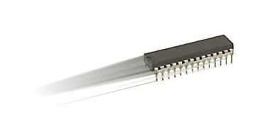
The first step is bend up all pins except for pins 7 and 14 on the 74LS00. The picture above shows the correctly
prepared 74LS00.
|
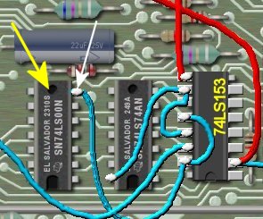
Next we need to locate the 74LS00 already on the motherboard. We will use this IC to piggy-back our new
74LS00 to this IC. The yellow arrow in the above picture shows the location of this IC. You should notice
that this IC already has a wire soldered to it on pin 7. Temporarily unsolder this wire as we will need to
solder our 74LS00 to it. Next solder pins 7 and 14 of the new 74LS00 to pins 7 and 14 of the existing 74LS00.
Next solder the wire we removed a little earlier back to pin 7. The picture below shows the new 74LS00
added and the wire replaced.
|
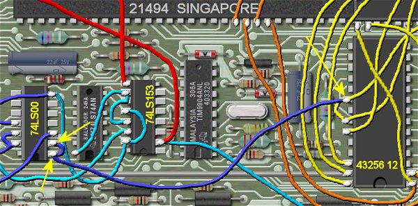
We will next solder a wire from pins 1 and 2 from the 74LS00 to pin 20 of the 43256 RAM IC. Refer to the
picture above. For the rest of this project we are only interested in the dark blue wires. There will
already be wires on pin 20 of the 43235 so be careful that don't loosen up one of the existing wires.
|
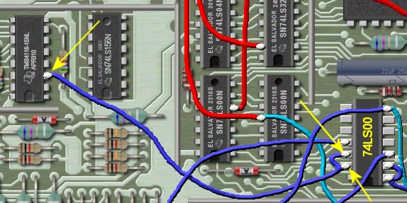
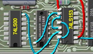
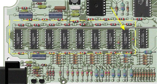
Now solder a wire from pins 12 and 13 from the 74LS00 to pin 3 of the TMS4116. The TMS4116 is one of the
eight console RAM IC's. This IC could possibly be a different number IC but the pinouts are the same. The below
picture shows the location of the TMS4116.
|
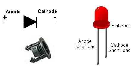
We are now ready to solder the remaining wires to the LED's. You will need to determine where and how you would
like to mount your LED's. You can pick up LED holders which make a nice mount for the LED's. The picture above
also shows an LED, and how you determine the anode (+) and cathode (-). Keep in mind that the cathode is
shorter wire, and has a flat spot near that wire.
|
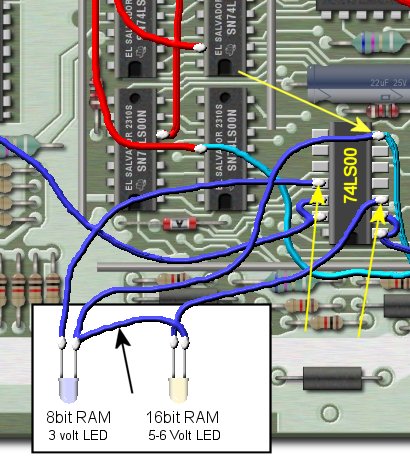
Refer to the above picture for the correct wiring, again, we are interested in the dark blue wires. Solder
a lenght of wire to pin 7 of the 74LS00, also solder back, on the same pin, the wire we temporarily removed earlier.
Next connect this wire to the cathodes (-) of BOTH LED's. This is the ground connection.
Now solder a wire from pin 11 of the 74LS00 and solder this to the anode (+) of the 3 volt LED. This LED will
show activity on the 16K of console RAM.
Solder a wire from pin 3 of the 74LS00 to the anode (+) of the 5-6 volt LED. This LED will show activity
on the 32K RAM which we added earlier.
That's it!
|
