|
Logic Gates
|
TRANSISTOR
To understand logic gates you must understand the transistor used in the construction of gates. Without
getting into a lot of physics, know that a transistor is made of three parts. This is shown in the above
picture as the two red and one blue section. Most transitors have three wires and one wire would be attached
to each of these sections.
One of the most basic parts in a computer circuit is a clock. Now this clock
doesn't really keep time (though it can) but is used to produce very fast, accurate pulses or signals. When
I say fast, I mean it. Pulses can be anywhere from 1/100,000 of a second to 1/1,000,000,000 of a second. As
humans we can't even imagine anything going that fast so it will suffice to say that computers are useful only
because they can do everything very fast.
|
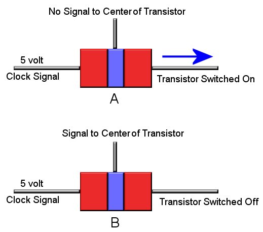
Back to our transistor. As can be seen above, one section of the transistor is connected to the clock. In most
computer circuits this will be a 5 volt signal. In "A" of the above picture the transistor is "on" because there
is NO signal to the center section of the transitor. So in other words when the clock sends the transistor
a pulse the transistor will also send out a pulse from its output.
Now notice in "B" of the picture the center section of the transistor is now recieving a signal. This in turn
turns "off" the transistor. This might seem backwards, but in the world of logic circuits it works out nicely.
It is very important that you understand the concept of a switching transistor to understand logic circuits. Make sure
you understand the above before moving on to logic gates.
|

NOT GATE
Logic Gates are the building blocks for all digital circuits. There are several of them, and we are
going to take a look at the three most used. If you understand these three you will have no problems
understanding the remaining ones as they are just extensions of these three. Logic gates are comprised
of the type of transistors described above.
Another concept we need to understand is the binary system. It is out of the scope of this page to teach
binary math, but knowing that the binary systems contains two numbers: 1 and 0 will suffice. Binary numbers
are the basis of all math functions performed by digital computers. Remember above when we discussed
transistors and how they can be switched "on" or "off"? Well, in binary if the transistor is "off" then we
consider that a "0". If the transistor is "on" then we consider that a "1". In fact this is the whole basis
to digital. Everything that happens in the digital world can all be summed down to being either 1's or 0's, and
nothing in between. On, Off, Yes, No, 1,0, no mediums, maybes, or any other numbers.
That's it, that is the magic of digital.
|
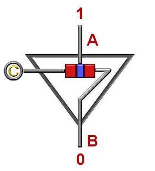
The picture above is that of a NOT logic gate (also know as an inverter). Notice that it contains only
one transistor. All logic gates contain an input and an output. This is shown by the "A" input, and "B" output in
the NOT gate below. The circle with a C in it is the clock signal.
Show below the NOT gate is it's truth table. Computer logic is based on a branch of mathematical
logic called Boolean Algebra. Truth tables are part of this and they show all the posiable outputs of a
paticular logic gate. As you will notice the truth tables will be larger for the other two logic gates will be
looking at. If you notice the truth table for the NOT gate shows that for an input(A) of 0 the output(B) is a 1,
while an input(A) of 1 results in an ouput(B) of 0. You can see why this gate is sometimes called an inverter, as
it simply inverts the output.
In our example above notice that a 1 is being input, and since this sending a signal to the center part of the
transistor it turns the transistor "off". This in turn switches off the clock pulse and outputs a 0.
On the other hand if we were to input a 0 then the transistor would be switched "on" and the NOT gate would
ouput a 1.
|
AND GATE
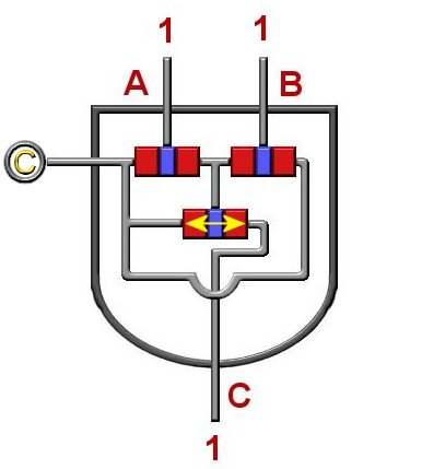
An AND gate is another of the basic building block logic gate. An AND gate consists of three transistors, and
as can be seen is more complicated than a NOT gate. Also notice that it's truth table is quite larger than
the NOT's. As it's name and truth table implies only when the inputs (A,B) are 1 "AND" 1 will you get an output(C)
of 1.
The yellow arrow on the lower transitor shows that this transistor is "on". Since the two upper transistors are
getting a signal they are both switched "off". If either one
of them would be switched "on" then their output would send a signal to the lower transistor's center section
which would switch the lower transistor "off" resulting in an ouput of 0. Make sure you understand why this is so.
|
OR GATE
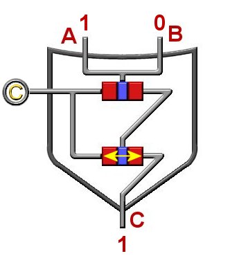
Pictured below is an OR gate. As the name and the truth table implies, if input(A) "OR" input(B) is a 1 then
the output(C) will be a 1. An OR gate consists of two transistors. In the example below input(A) is 1 and
input(B) is a 0. Since one of the inputs is a 1 then the output(C) is a 1.
Since one of the inputs is a 1 it sends a signal to the center of the upper transistor which turns it "off".
Since the upper transistor is switched "off" no signal goes to the center part of the lower transistor which
means that it is switched "on" which results in an output of 1.
|
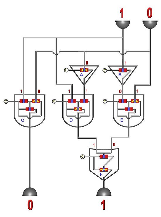
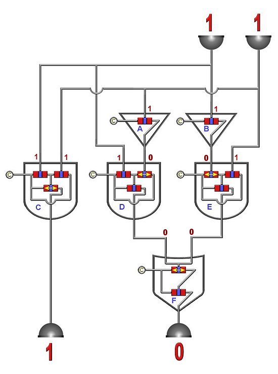
Adder Circuits
Below are two adder circuits. See if you can follow the "bits" through. Hint: Any gate transistor that has
a yellow double arrow is "on".
|