 |
Alpha Lock / Joystick Fix
|
With this project completed you will never need to worry about the alpha-lock key being up or down
when you are using joysticks.
This is a very simple project and can be completed with the keyboard installed. You will need to remove
the bottom cover from the console.
The only tools you will need is a soldering iron, and an x-acto knife. You may need a short piece
of shrink tubing, depending upon your paticular style of keyboard.
You will need a 1N4148 Diode.
TI used several different manufacturers to produce their keyboards so the pictures I have below might or
might not match exactly, but the procedure should be the same for all them.
|

|
|
Please make sure that all wiring and soldering is double checked before re-applying power. Though computer components are pretty hardy some do not take to being
wired up backwords or incorrectly. I have done my best to make sure that all diagrams
and instructions given here are correct, but I can not be responsible for any damage
an incorrect upgrade might cause. Also keep in mind that this will probably void any warranty :>).
|
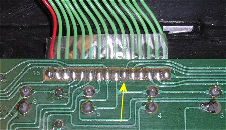
The keyboard attaches to the TI motherboard with a 15 pin connector. The above picture shows the solder
side of that connector. The yellow arrow is pointing at the number "6" connector. This is important
because it this connector that the diode needs to be soldered too, and is the pin that one side of the
alpha-lock switch connects to.
|
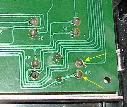
This picture shows the lower right hand side of the bottom of the keyboard. The two yellow
arrows are pointing at the solder connections for the alpha-switch.
|
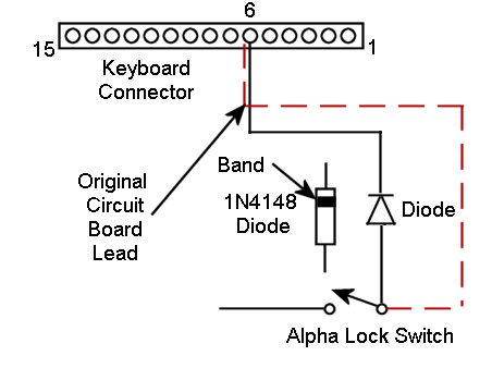
This picture shows the schematic for this project. Note the direction of the diode, and that you
must remove a part of the lead that originaly ran to from the alpha-switch and the connector 6 on the keyboard connector.
|
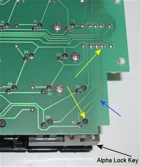
(This picture is of a HI-TEC keyboard)
Even though the above picture shows the keyboard out of the console there is no need to do this. The
black arrow shows where the alpha-lock key is for reference. The two yellow arrows shows where we
will be soldering, and the blue arrow shows the lead we will be cutting.
|
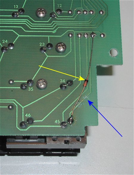
(This picture is of a HI-TEC keyboard)
The above picture shows the diode soldered in it's correct place. Notice that the black band on the
diode goes away from the switch. This is noted by the yellow arrow. You will also need to place a
small break in the lead, the blue arrow points to the correct lead. Simply use the knife (careful now!)
and cut away a small piece of the lead so there is no continuity. The blue arrow is actually pointing
at the place where I cut mine. If you look close you should be able to see my knife marks.
|
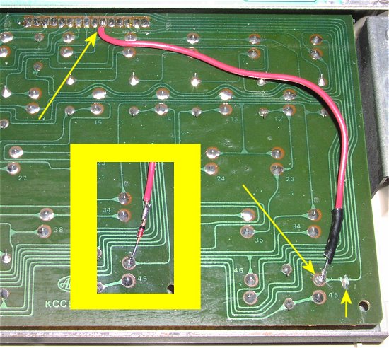
(This picture is of a ALPS keyboard)
This paticular keyboard needed a wire to reach the connector, and the above picture shows this. I soldered
the wire to connector "6", soldered the diode (noting the direction of the band) to the wire and
alpha-lock switch, and then cut a small piece of the circuit board lead out. The 3 yellow arrows show
these 3 steps. I put a small piece of the shrink tubing around the diode. The inset in the picture
just shows the diode and wire before the shrink tubing was applied.
Again, your keyboard may differ from the pictures above but with the information provided above you
should be able to figure out how to add the diode to your style of keyboard.
That's it! Told you, not too difficult.. now, who is ready for a game of Parsec!
|
