|
Horizon 32K Mod to
Replace PE-Box 32K Card
|
This project will allow you to add 32K of RAM to the 2000 series Horizon Ramdisk Cards,
allowing you to remove the 32K memory card from the PEB.
The plans for this project were designed by John Guion and Bud Mills.
|
A kit with the parts for this project can be ordered from here
|

|
|
Please make sure that all wiring and soldering is double checked before re-applying power. Though computer components are pretty hardy some do not take to being
wired up backwords or incorrectly. I have done my best to make sure that all diagrams
and instructions given here are correct, but I can not be responsible for any damage
an incorrect upgrade might cause. Also keep in mind that this will probably void any warranty :>).
|
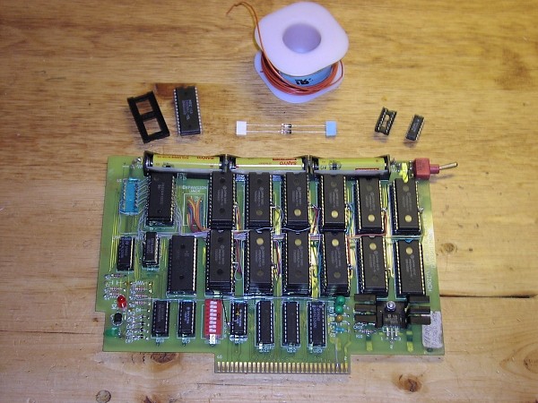
The above picture shows the Horizon 2000 series Ramdisk, and the parts needed to complete the project.
Parts List:
1 - HM62256-LP12 or 43256-12L 32K RAM
1 - 74LS08
2 - 1N34A Diodes
1 - 28 pin socket
1 - 14 pin socket
Wire
|
I choose to use sockets instead of just soldering the chips on top of U11 and U18. This way all
you have to do is remove the new IC's from their sockets and you disable the upgrade if you find the
need to.
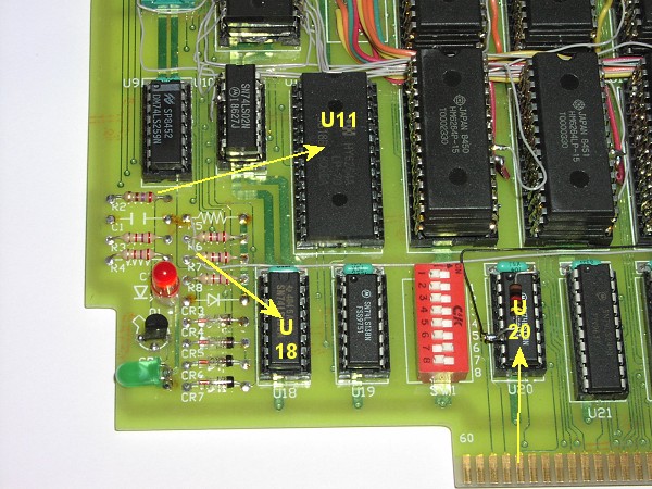
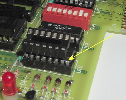
The 3 IC's we will be interested in are marked by the arrows. They U11, U20, and U18. I started by
removing U11 and U18 from their sockets. Before soldering the new sockets to these IC's certain pins
need to be bent up so they don't touch the existing pins on the IC's. I also removed my batteries
before I started, just to make sure that I didn't short anything. Be sure to back up your card
if you decide to do this.
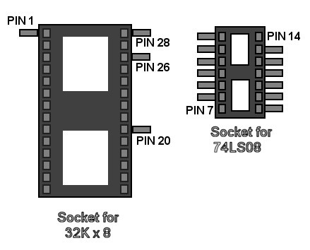
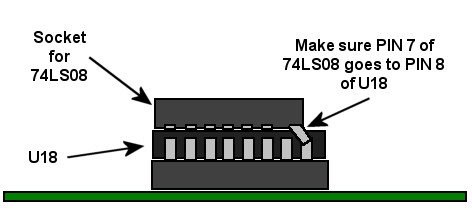
For the 28 pin socket, pins 1, 20, 26, and 28 need to be bent up. For the 14 pin socket all pins
except pins 7 and 14 need to be bent up. See below picture for more details on the pins.
|
After all the correct pins have been bent up, I proceded to solder the sockets to the existing IC's.
Pin 7 on the 14 pin socket needs to be bent back some as it needs to be soldered to pin # 8 of U18. Pin
14 of the 74LS08 solders to pin 16 of U18.
The picture above shows this. The below picture shows this again.
|
The picture above shows both sockets (shown by yellow arrows) soldered to the chips.
|
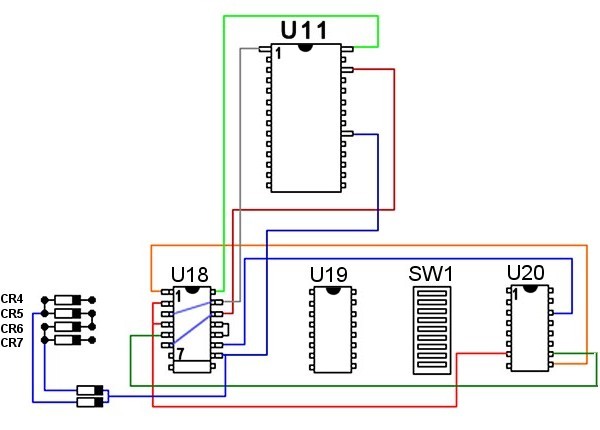
The above diagram shows the wiring diagram. Be careful here so you don't bridge any of the pins on
IC's. Connect the wires as follows:
From the 74LS08 Socket
pin 1 to pin 9 of U20
pin 5 to pin 10 of U20
pins 3 and 13 to pin 1 of U11
pin 8 to pin 20 of U11 and diodes
|
|
pin 14 to pin 28 of U11
pin 2 and 4 to pin 7 of U20
pin 9 to pin 14 of U20
pin 6 and 12 to pin 26 of U11
|
Connect pins 10 and 11 of the 74LS08 socket to themselves.
Next solder on the diodes as shown in the above diagram. Make sure you have the bands pointing at
the 14 pin socket.
|
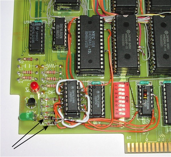
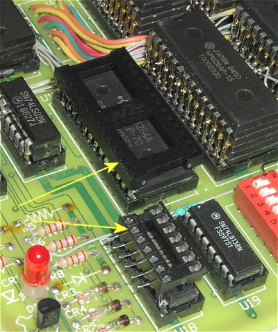
The above pictures shows the completed wiring. Notice also, that I have inserted the 2 new IC's.
The arrows are pointing at the 2 new diodes.
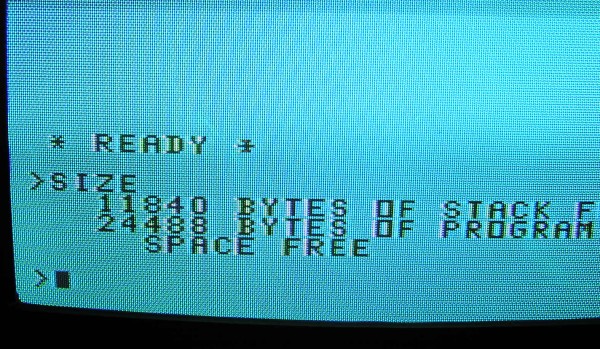
Be sure to double check all the wiring and solder joints before placing the card in the PEB. If you are sure
that everything looks ok, replace the batteries, and place card into the PEB. Be sure you have removed
the existing 32K memory card. Power up, and use the Extended Basic cartridge. Type "size" at the prompt
and make sure you see "11840 BYTES OF STACK FREE, 24488 BYTES OF PROGRAM SPACE FREE.
The results should like the screen shot below.
|