 |
PEB 12 volt 2 Amp
Power Upgrade/
Fuse Replacement
|
The PEB's power supply was designed to supply 12 volts for a single drive installed in the PEB. This upgrade
will increase the 1 amp, 12 volt output to a 2 amp 12 volt output. It is a fairly easy project, the toughest job
being, getting to the power supply. While the PEB is apart you may wish to change out the noisy cooling fan.
Instructions for replacing this fan and how to disassemble a PEB can be found
here.
The idea from this project came from a project in the April 1990 MICROpendium, and the original article was written by
Eric W. Bray, M.D. and was later modified by
John Creviston as to use parts available today.
Also at the bottom of this page I show the "Mystery of the hidden fuse". TI decided to place the fuse inside the
transformer. If you have a PEB where the 115vac fan still works but nothing else, then more than likely it is
a blown fuse.
|

|
|
*** You will be working with 110 volts in this project so it is very important that you remove the
power cable from the PEB before going any further.***
Please make sure that all wiring and soldering is double checked before re-applying power. Though computer components are pretty hardy some do not take to being
wired up backwards or incorrectly. I have done my best to make sure that all diagrams
and instructions given here are correct, but I can not be responsible for any damage
an incorrect upgrade might cause. Also keep in mind that this will probably void any warranty :>).
|
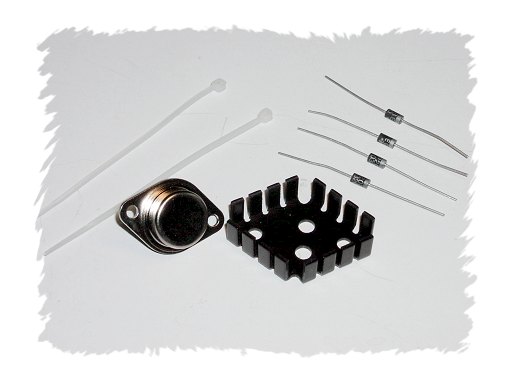
The above pictures shows the parts needed to perform the upgrade. John includes two wire ties
in this kit, which are used for the fan project, and are not used for this project.
The parts needed are:
1 - 12 volt 2 Amp regulator
The 2 Amp regulator can be found here.
4 - 2 amp diodes --
Rectifiers 3.0a Rectifier General Purpose
1N5402
1 - heat sink
Some Heatsink compound
|
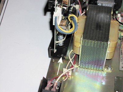
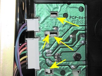
Once you have the PEB disassembled you will need to remove 2 screws that hold the power supply to the case.
The arrow is pointing to one of the screws and there is one more on the opposite side. A longer phillips
screwdriver comes in handy here.
|
There are also 3 connectors attached to the power supply circuit board. The above picture points to them.
|
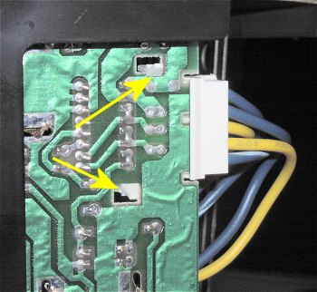
These connectors do not just "slide" on, and they must be "unclipped" on the back of the circuit board. The
above picture points to the clips.
|
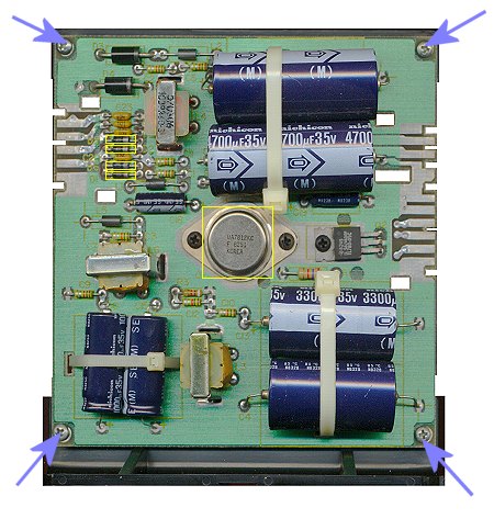
After the above steps you should be able to remove the power supply from the PEB. You will now need to remove
the 4 screws from the circuit board which holds it to the plastic support.
The above pictures shows the components that will need to be unsoldered and removed. They are the ones with a
yellow box drawn around them, and are 4 diodes and the large voltage regulator. Remove the 2 screws which bolt
down the regulator and set them aside as we will re-use them.
|
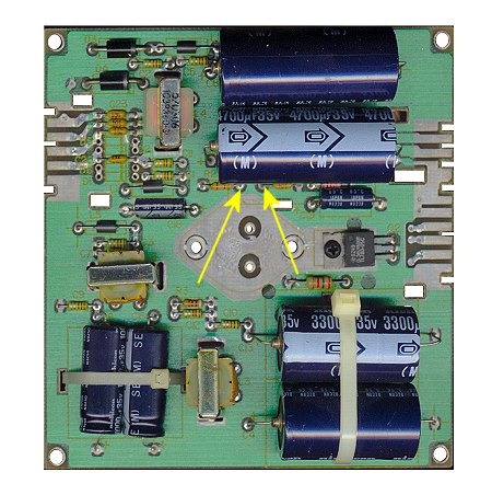
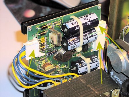
The above picture shows the parts mentioned above removed. The two yellow arrows are pointing at two solder
joints on the power supply. Be careful when fitting the new voltage regulator's heat sink that it does not
touch either one of these. If needed you can file a bit of the heat sink to make sure it will
not short against these. The one John provides
will fit without modification.
|
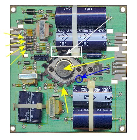
We are now ready to solder on the replacement parts. First install the 4 2 amp diodes. It is very important
that these are installed correctly. You will notice that the diodes have a band close to one end. Make sure
that all of these bands are on the right as viewing them in the picture above.
Next we will install the new 2 amp voltage regulator. First we will set the heatsink on top of the
circuit board with a little heatsink compound spread on the bottom of the heatsink. Again make sure that the
heatsink will not short any connections on the motherboard. Next place some heatsink compound on the bottom
of the regulator and place it on top of the heatsink. Using the two bolts screw down the regulator securely to the
circuit board.
The white arrow and box above shows where you want to make sure that you are not shorting anything on the
circuit board. The blue arrow and circle shows an area where the heatsink may touch a little. This is ok
here (blue area) as this is a ground connection, same as the heatsink.
After the heatsink is bolted down, solder it's two leads to the bottom of the circuit board.
That's it!! Give all your soldering joints another inspection, and we will be ready for testing.
If you wish, and promise to very careful, you may test the power supply before putting everything back
together. Go ahead and put the circuit board back in it's place and tighten the 2 screws. Replace the
three wire connectors which you removed earlier. Connect your power cable, and keep your hands out of the PEB!
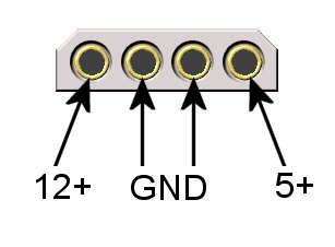
Flip the switch, and measure the voltage on the drive power connector. You should get voltages close
to the values shown below.
Turn off the PEB, and REMOVE the power cable. Yes, that means you, remove the power cable :>).
At this point you can reassemble your improved PEB. If you are going to be installing two drives into your
PEB I have a project which can be found here.
|
Replacing the Fuse

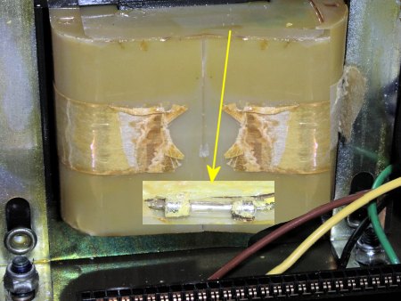
Yes there is a fuse in the PEB! It is actually inside the transformer. So to be able to replace it you will
need to remove some of the plastic which surrounds the transformer. The picture above shows the location of the fuse
using "x-ray" vision. I took this picture using a pair of those x-ray glasses I purchased from a comic book
many years ago :>)..
There is NO reason to replace the fuse unless you suspect that it has blown. Again, the symptoms would be
that the 115vac fan runs but nothing else appears to be getting power.
The replacement fuse needs to be a 3 amp fast-blo with wire leads.
|
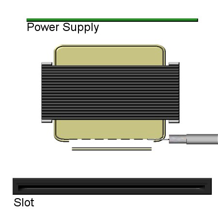
Carefully cut the plastic away as shown in the above picture. The most important thing here is to not get
carried away and cut any wires inside the transformer. Go slow and easy. This plastic is very brittle, and
it broke off more than it actually cut. I can't see any reason to worry about replacing the plastic so I just
broke off enough of it to be able to get to the fuse.
Simply de-solder the old fuse and solder in the new one. A fuse has no polarity so it does not matter which
direction you solder it in.
|
