 |
Speech Synthesizer
in Console
|
This is another "fun" project that is not difficult to do. The hardest part is that it takes some
close, detailed soldering. No "Soldering Guns" here! Make sure you have a very fine soldering tip, and
some fine solder, the 1/4" size just won't do it!
You will need in addition to the the fine tipped soldering iron, and small diameter solder, a piece of
ribbon wire with 17 wires. A color wire ribbon would be the best (used here), but you could even
use a floppy drive ribbon. Just split it so you have 17 wires. The ribbon needs to be around 10
inches long. You will also need a small amount of double sided foam tape. This is used to secure
the speech synthesizer to the TI motheboard's metal shield.
|

|
|
Please make sure that all wiring and soldering is double checked before re-applying power. Though computer components are pretty hardy some do not take to being
wired up backwords or incorrectly. I have done my best to make sure that all diagrams
and instructions given here are correct, but I can not be responsible for any damage
an incorrect upgrade might cause. Also keep in mind that this will probably void any warranty :>).
|
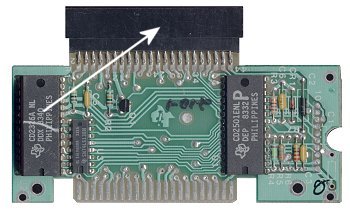
The first step is to remove the Speech Synthesizer (from now on known as the SS) from it's case. This
is acclomplished by removing the 2 screws from the bottom of the case. Now remove all the metal
shielding from the SS circuit board. You should be left with what is pictured above.
Remove the connector (pointed to by arrow), by de-soldering all the connections. You will need to
do this on both the top and bottom of the SS circuit board.
|
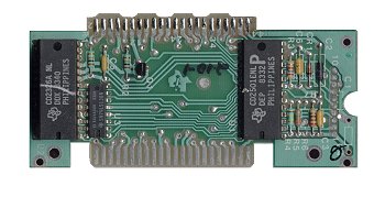
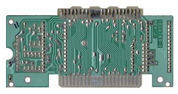
When you have removed the connector you should be left with what is pictured above. This is a
picture of the top and bottom of the SS circuit board.
|
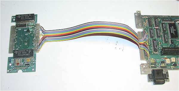
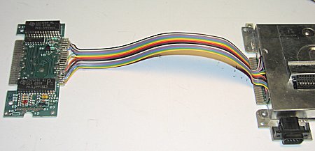
I thought it might be time for a shot of what the end goal is. The above picture shows the wiring completed.
This should give you a pretty good idea of what we are after. All wires on the motherboard side
are soldered on the top, while on the SS board wires are soldered on the top and bottom. I consider
the top of the SS circuit board with the chips the "Top". (Hey, it's my web page :>).
|
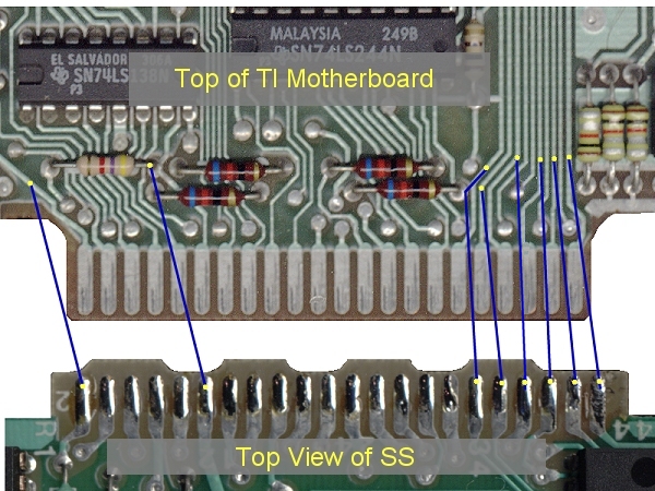
This shows the point to point wiring details for the top of the SS board.
|
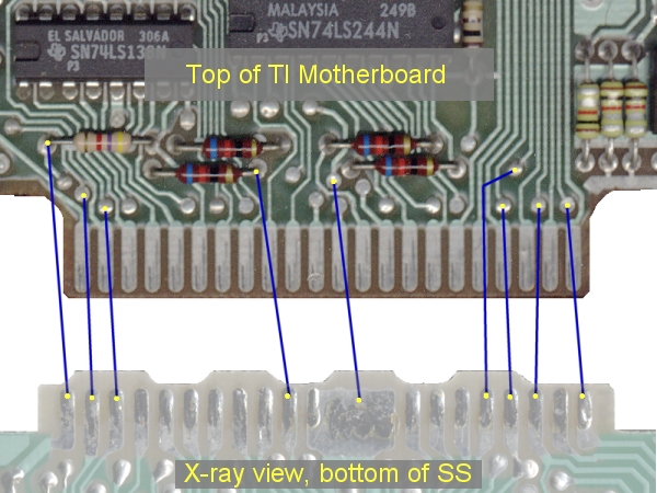
A little information is needed to describe the above picture. What you are looking at is the top of the
TI motherboard, and the BOTTOM of the speech synth. Imagine you have x-ray vision.. you are looking through
the top of the speech synth but only seeing the bottom connections.
There are 8 wires which solder on the top of the SS, and 9 wires which solder to the bottom of the SS.
Soldering on the SS is pretty easy as there is plenty of room, and it is pretty sparse. The motherboard end
contains many more components, and the connection areas are quite small. This end will require much
more careful soldering.
|
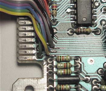
This picture shows the fine detail of some of the solder joints on the TI motherboard.
|
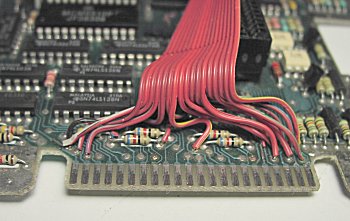
Make sure when soldering the motherboard end of the cable you leave the wires far back enough to
to allow the shield back on. The above picture shows this, also on the two wiring pictures I have
placed yellow dots in the approximate locations for soldering.
When you have completed the soldering of both ends of the ribbon cable, check all connections
with an ohm meter or continuity checker, using the wiring pictures above.
|
This picture shows the completed wiring with the shield placed on. Be careful handling both pieces
at this point to make sure you don't break a wire off.
|
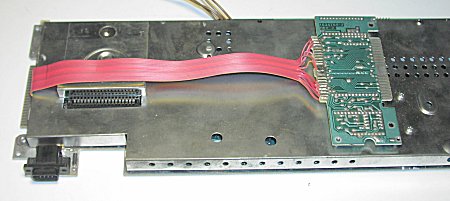
Now fold the wire over the shield as shown in the above picture. Use foam tape to secure the
SS to the shield, taking care that no part of the SS touches the metal shield.
Re-assemble your console, test your installation, and enjoy a nice long talk with your computer!
|
