 |
Instructions for 80 track
Upgrade Kit
|
This upgrade kit for the standard TI disk controller card allows 80 track drives to be
used, such as a 3 1/2" 80 track floppy. The modified code supports 40 and 80 tracks
for SSSD and 80 tracks for DSSD, whatever drive is designated as the 40 track drive, either #1 or #3, supports 40 track DSDD.
Please read the docs file included in the zip file below (bottom of page) for more information about how these work.
This is the reason for the large PROMs and
the switch. John added the switch to his kit so you can switch back and forth between these
two modes.

NEWS FLASH(April 5, 2005)
These kits are no longer avaiable from John. For those of you who wish to build your own "KIT" go to the
bottom of the page. I have drawn the wiring diagram for the switch option. Also you can download the
PROMS if you have a way to burn your own eproms.
|
Tony Knerr is credited for writing the code for the PROMS!, Thanks Tony!!!
The code is used with Tony's permission.
Please make sure that all wiring and soldering is
double checked before using the board.
Though computer components are pretty hardy some do not
take to being wired up backwords or incorrectly.
I have done my best to make sure that
all diagrams and instructions given here are correct,
but I can not be responsible for any damage an
incorrect upgrade might cause. Also keep in mind that
this will probably void any warranty :>).
|
Assembly Instructions
Start by testing your disk controller with the full diagnostics test in the Disk Manager II cartridge.
Unless it passes, do not continue
Remove the 4 screws from the case and remove the disk controller from the case. Remember to take ESD precautions.
|
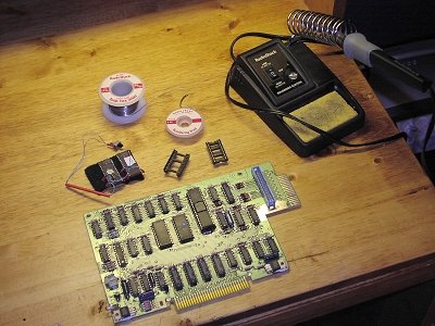
Figure 1.
Figure 1 shows the tools and parts needed to complete upgrade.
1. Soldering Iron
2. Solder
3. Desoldering Braid
4. The Upgrade Kit
5. 2 24 pin Sockets
6. The disk controller card
|
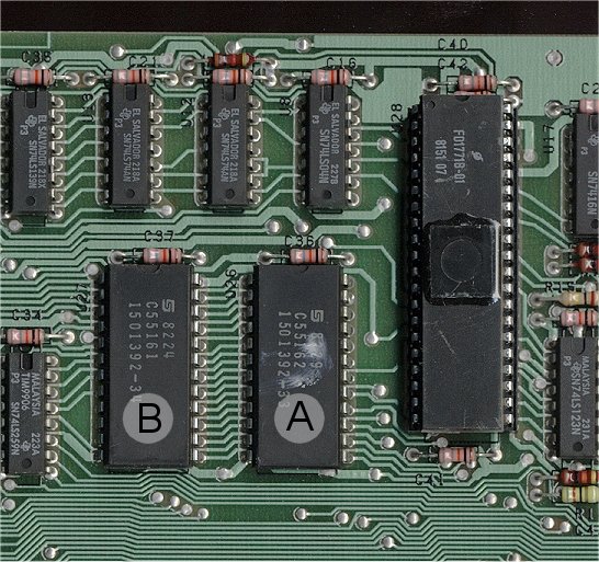
Figure 2.
Figure 2 shows the locations of the two ROMs that will be removed. They are marked A and B.
Use the desoldering braid, or a desoldering tool to remove the solder from both of these ROMs.
An alternative method would be to cut the pins, and then de-solder each pin. Of course this will pretty much destroy the original ROMs.
|
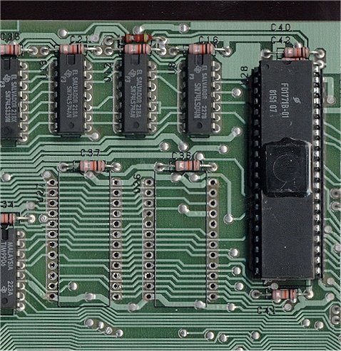
Figure 3.
After the ROMs are out, inspect the area for damaged traces
or solder bridges. Be very thorough, and clean the board with flux remover.
Figure 3 shows the board with the ROMs removed and cleaned up.
Check the board by placing it in the pe-box slot where it will reside. Be sure to leave the power off for 2 minutes before installing or removing a board. Next, power on the system and make sure the console will power up to a normal screen. If it does, then power down and remove the disk controller
|
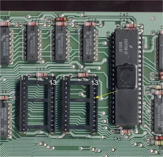
Figure 4.
Solder in the 24 pin sockets. Make sure you add enough solder so that some flows through to the
other side of the board (refer to figure 5). Inspect your work for too much or too little solder, again,
clean the board.
Check the sockets with an ohm meter or continuity tester. You will need to have some pretty sharp probes to fit
into the sockets. Continuity should show on all like pins EXCEPT the one show by the yellow arrow. Pins
marked 1 and 1 should show continuity, pins 13 and 13 should also show continuity. Check all pins
in this manner. If a set of pins does not show continuity then add a little more solder to these pins from
the back of the board. (You can't solder from the top as the sockets cover them).
Check the back of the board to make sure no solder has bridged. Check for solder bridges between
pins next to each other and across from each other.
|
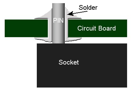
Figure 5.
Figure 5 shows a cutaway of the circuit board. Notice that solder must flow through hole as the
24 socket pins are soldered on the top of bottom of this board. Board in figure 5 shown upside down
in the normal soldering position.
|
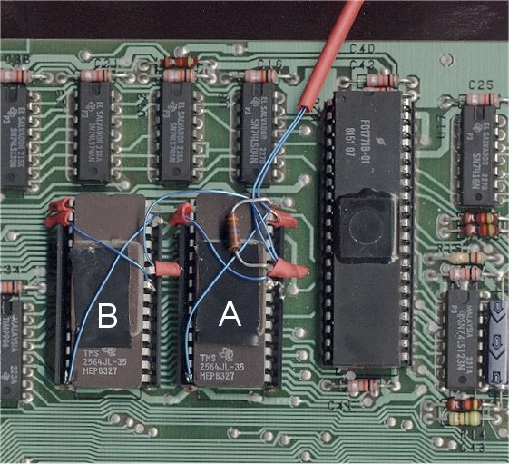
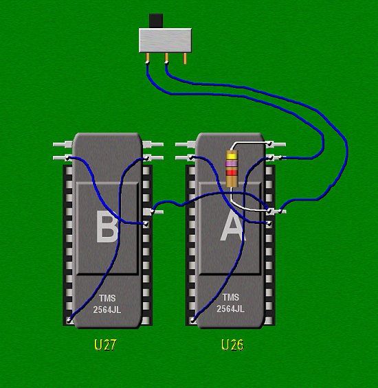
Figure 6.
Install the two ICs into the sockets with A closer to the 1771, and the top pins of the
PROMs (the two on each side with the red tubing) overhanging the top of the socket with the bottom pins
of the PROM going into the bottom pin of each socket. Only 23 of the 24 pins in the socket willl
have a ROM pin inserted into them. The pin on each rom with the red tubin, and the wire connected is bent
out slighty as it is not to be seated into the socket.
See figure 6.
|
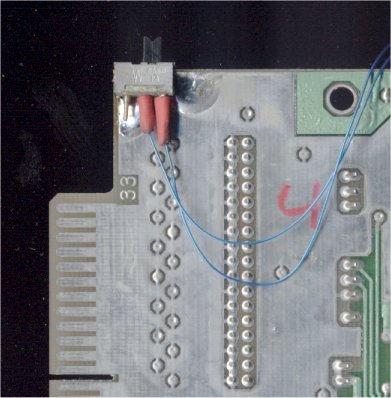
Figure 7.
Route the wires to the switch over the top of the board and mount the switch by solder
to the extension of the card, close to the top so it will not interfere with anything and have
the slide accessible to you. See figure 7
|
Testing the Installation
For the first test set the switch so that the slide is over the end without the wire. This should be the original DSR. Install the case on the card, and the card in the pe-box and connect the drives.. Watch the front of the pe-box as you power on the system. You should see a brief flash of the disk controller led. If you do continue.
Select DM2 and attempt to catalog DSK1, the LED on the drive should light, if it does try all of the other drives connected.. Choose DISK COMMANDS : INITIALIZE in the DM2 and try to format a disk in the 80 track drive to 40 tracks DSSD. If it passes, continue.
Power off and move the switch to the 80 track "on" setting (figure 7 shows the switch in this mode). Power on and try to format a disk in the 80 track drive to 80 tracks DSSD. If it passes run a full diagnostics pass. It is important that you do this.
For the last test use the floppy from the previous step, or a new UNFORMATTED DISK FOR THIS STEP, With the switch in the 80 track position, format a disk in the 80 track drive to 40 tracks DSSD. If should fail starting at sector 360. If it does you are finished and ready to use your modified controller.
|
Build your own Kit
If you need the PROMS and you have a "burner" click here. to download them.
|
