 |
TI-99 Console Speedup
|
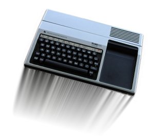
This project allows you to increase the speed of your console from 3mhz to 3.58mhz. It might not
sound like a big increase but this is a 20% increase in speed and it is easily noticable. Of course, if
there is one thing I have learned in the world of computers is that everything is a compromise.
The same goes for the speed increase. There are bound to be certain programs that use console timing
and these will probably not work, or be flaky at the least. But not all is lost! This project also
contains a switch which will allow you to choose the faster crystal or the original one.
John informed me that the RS232 card baud rate is dependent on the timing of this crystal, which
means you will end up with some wierd baud rates being generated. John has a fix for this and will be
getting the information to me on how to update the PROM on the TI RS232 card.
One last issue: If you DO NOT have a 12mhz crystal on your mother board then you CAN NOT continue.
Some motherboards used a much faster crystal and used an oscillator circuit to produce the
correct frequency. I don't know how to check this without just looking on the motherboard.
|

|
|
Please make sure that all wiring and soldering is double checked before re-applying power. Though computer components are pretty hardy some do not take to being
wired up backwords or incorrectly. I have done my best to make sure that all diagrams
and instructions given here are correct, but I can not be responsible for any damage
an incorrect upgrade might cause. Also keep in mind that this will probably void any warranty :>).
|
You will need to locate a 14.31818 crystal. Contact John here,
he should be able to get these crystals for you. They were pretty common in the "old days" and you might
even have some old boards laying around which contains one of the above crystals. I tried using a 16mhz crystal, and
though Parsec and some others games played just fine (though faster), I had trouble in writing code in
the console. The 14.31818 has so far not given me any problems with anything I tested it with (see note
about the RS232 card above).
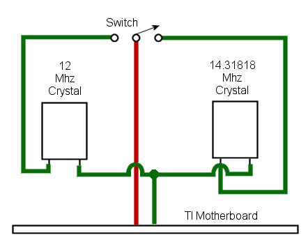
The above picture shows the schematic for this project.
|
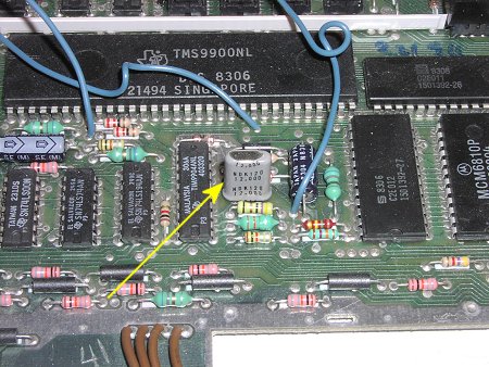
You will need to completly disassemble your console, if you need assistance with this go
here. The picture above
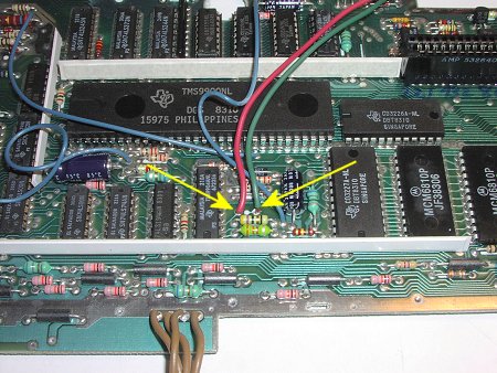
shows the location of the crystal on the TI motherboard. Again, make sure that this crystal is
marked 12.000 as this one is. If it is not a 12mhz crystal then you can not continue (see note above).
|
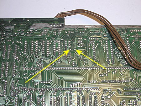
The two yellow arrows in the picture above point to the solder connections for the crystal on the
solder side of the motherboard. When de-soldering the crystal keep in mind that we will be re-using
this crystal.
|
I have now soldered 2 wires into the holes that used to hold the crystal. I used 2 different color
wires as it is important that we solder the wires to the correct leads on the crystals. Notice in the
schematic above that the "red" wire MUST go to the left side of the crystals as they are viewed from
the front (front, being the side with writing).
|
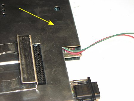
In this picture I have re-installed the shielding on the motherboard and have the 2 wires exiting
at the opening in the shield. The yellow arrow shows the approximate locations where we will be
taping down the crystals.
|
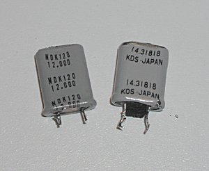
This pictures shows the "front" of our two crystals.
|
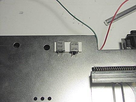
I used double sided foam tape to hole the crystals in place. This seems to hold them very well, and
the thickness of the tape holds them away from the metal. Notice that both crystals are mounted "front"
up. The above picture should give a pretty good idea as to where to tape them.
Do not cover the hole to the left as a screw does go through this hole.
|
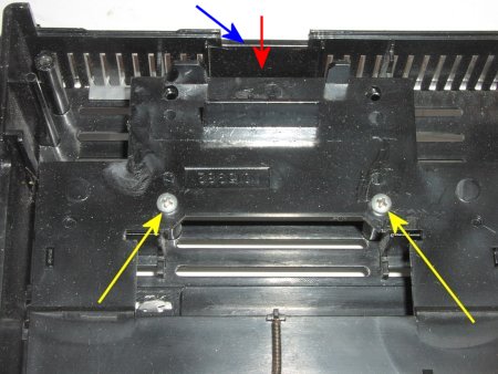
Next you need to decide where to mount the switch. I wanted mine hidden on the back of the console, though
you could put yours anywhere, just try to keep the wires as short as possible. The area I chose
is right above where the power cable plugs in. If you do choose this area just make sure that
you drill the hole for the switch high enough to miss the power connector.
To work in this area I needed to remove the plasic part where the cartridge connector goes through.
This is easily done by removing the 2 screws holding it on. The above yellow arrows show the 2 screws.
The red arrow shows where I drilled for the hole (not there yet), and the blue arrow is showing the
cutout for the power cable connector. I chose this area because it is solid plastic, where, if you
notice the area surrounding it is all vented.
|
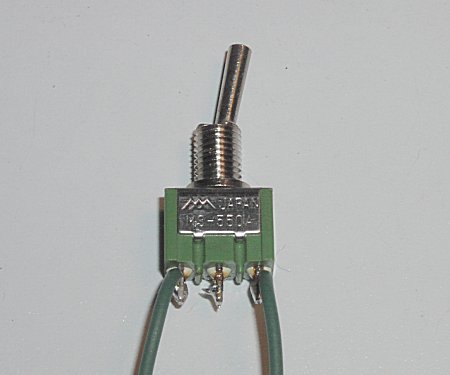
Here is my switch showing a couple of wires already soldered on. This makes installation much easier.
The "red" wire will be soldered on to it's center post after it is attached to the console.
It is a SPDT toggle switch.
|
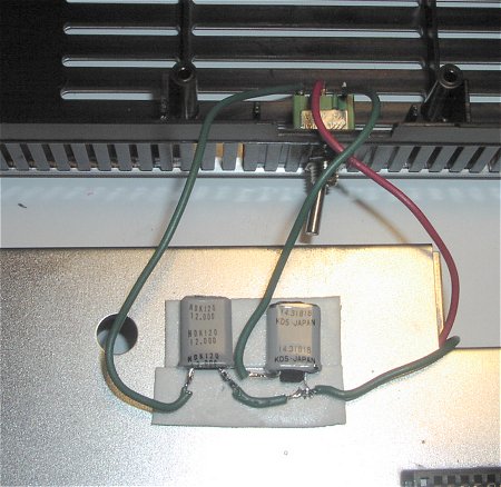
The switch has been mounted to the top of the console. I have the console top upside down.
The red wire has now been soldered to the center post on the switch, and the green wires have
all been soldered on.
The above picture shows all the wires soldered on. Make sure you follow this exactly as shown.
Just to make sure nothing touches the metal sheild I added another piece of foam tape under the wires
|
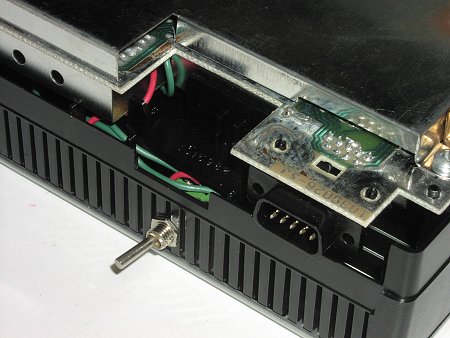
This picture shows the completed installation. When you mount the motherboard back in the
console take care that you don't pinch any wires. You may wish to mark the switch with a label showing the TIrbo and Normal
settings.
|
I ran some sample programs, timed them and they all showed around a 20% increase in speed.
|
